Interface hook-up data sheet for Njord B
Norsok Standard Z-015
General information
Plant type: Fast innretning
Electrical
Power * | Volt [V] | Frequency [Hz] | Phase Current [A] | Neutral Loaded [Yes/No] | System earth ** | Short circuit level min [kA] | Short circuit level max [kA] | Distribution protection fuse [A] | Distribution protection earth fault [mA] | Connection platform (Description / Type) | Connection temporary equipment (Description / Type) | Area (Module Number / Room Number) |
|---|---|---|---|---|---|---|---|---|---|---|---|---|
| Main | 400 3P+N+PE | 50 | 63 | No | S | 63 | 30 | Stahl-Syberg 8579/31-506-S001 | 8579/12-506 | Y00 Upper Deck | ||
| Main | 230 1P+N+PE | 50 | 16 | Yes | S | 16 | 30 | Stahl-Syberg 8570/15-306 | 8570/12-306 | Y00 Upper Deck |
*
Main - Main Power,
Emg - Emergency Power,
Ess - Essential Power,
UPS - UPS Power
**
S = Solidly (direkte jordet),
I = Isolated (isolert)
R = Resistor (resistansjordet)
Instrument
Function | Signal type | Connection platform (Description / Type) | Connection temporary equipment (Description / Type) | Area (Module Number / Room Number) |
|---|---|---|---|---|
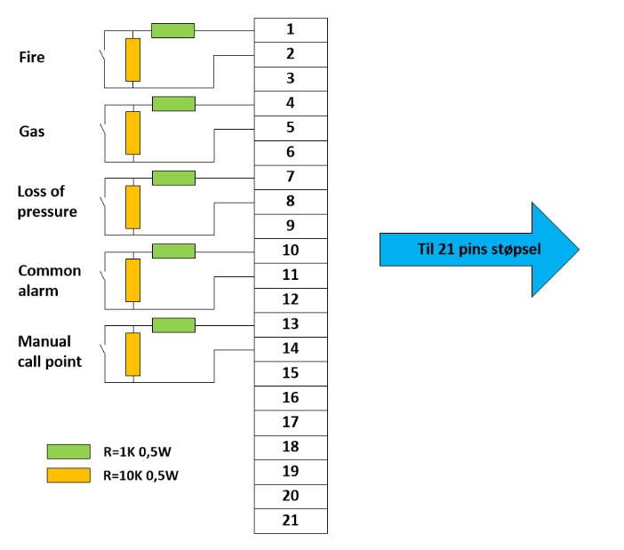
| Loss Of Pressure | NO-kontakt (kontakt = alarm) Note 1: Må ha motstand i parallell og serie! Se typisk krets nedenfor. | GHG 511 4906 R3001 6h Pin 7, 8, 9 | GHG 591 2201 R0002 6h Pin 7, 8 | Y00 Upper Deck |
| Fire | NO-kontakt (kontakt = alarm) Note 1: Må ha motstand i parallell og serie! Se typisk krets nedenfor. | GHG 511 4906 R3001 6h Pin 1, 2, 3 | GHG 591 2201 R0002 6h Pin 1, 2 | Y00 Upper Deck |
| Gas | NO-kontakt (kontakt = alarm) Note 1: Må ha motstand i parallell og serie! Se typisk krets nedenfor. | GHG 511 4906 R3001 6h Pin 4, 5, 6 | GHG 591 2201 R0002, 6h Pin 4, 5 | Y00 Upper Deck |
| Other | NO-kontakt (kontakt = alarm) Note 1: Må ha motstand i parallell og serie! Se typisk krets nedenfor. | Common Alarm: GHG 511 4906 R3001 6h Pin 10, 11, 12 Manual Call Point: GHG 511 4906 R3001 6h Pin 13, 14, 15 | Common Alarm: GHG 591 2201 R0002 6h Pin 10, 11 Manual Call Point: GHG 591 2201 R0002 6h Pin 13, 14 | Common Alarm: Y00 Upper Deck Manual Call Point: Y00 Upper Deck |
| ESD Battery System |
Telecom
Function | Signal type | Connection platform (Description / Type) | Connection temporary equipment (Description / Type) | Area (Module Number / Room Number) |
|---|---|---|---|---|
| Data (Fibre) | Panel contact container and Utility station end: 4-channel panel contact 3 pc. Probeam Jr 4 2X699251-0-001 1 pc. 321/B M25 EEx NP brass ø13,0 -20,0mm | Drum: 4-fiber field cabel, PBJR-PBJR, 9/125 Prod.nr: 3-904MIL9-3-050 Prod.name: 4-fiber PBJR plugg- PBJR plugg, 9/125 50m coiled on drum, plug both ends Foss AS, Drammen | Y00 Upper Deck | |
| PA | Socket: STAHL 8570/11-404 4h (yellow) Compatible type for above | Plug: STAHL 8575/12-404 4h (yellow) Compatible type for above | Y00 Upper Deck | |
| Telephone | Socket: STAHL 8570/11-410 10h (green) | Plug: STAHL 8575/12-410 1Oh (green) | Y00 Upper Deck |
Utilities
Function | Pressure [bar] | Amount/Flow [max capacity] | Connection - type | Connection - diameter | Connection - material | Area (Module Number / Room Number) |
|---|---|---|---|---|---|---|
| Plant Air | 8,9 | |||||
| Instrument Air | ||||||
| Seawater | ||||||
| Drain | ||||||
| Other | ||||||
| Sprinkler | ||||||
| Freshwater | 9,7/7,0 |
Lifting capacity offshore cranes
No entries to show.
Comments
KORTSLUTNINGSNIVÅ
Verdiene vil være ved kortslutning i selve tavlen.
Kortslutningsnivået i/ved tavlen i det midlertidige utstyret vil være lavere.
Ved beregning av kortslutningsnivå kan følgende parametre brukes:
* Fra installasjonens hovedtavle og via fast opplagt kabel til stikkontakt/tilkoplingspunkt for midlertidig utstyr 3x25mm2 - 50 m.
* Fra installasjonens stikkontakt/tilkoplingspunkt for det midlertidige utstyret og via bevegelig kabel til utstyret 3 x 16mm2 -35 m.
SHORT CIRCUIT LEVEL
Values reflect short circuit level inside the switchboard
Regarding switchboard for temporary equipment the short circuit level inside or at the switchboard will be lower
When calculating the level of the short circuit following parameters can be used:
* From the facilitys main switchboard and via fixed cabling to the socked/connection point for temporary equipment; 3x25mm2 - 50 m.
* From the facilitys socked/connection point for temporary equipment and via flexible cables to the equipment; 3 x 16mm2 - 35 m.
Additional information
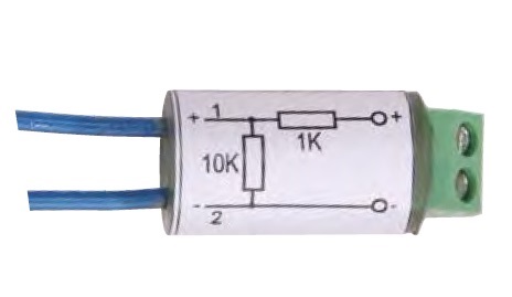
På Njord B er det sløyfeovervåkning på alle B&G sløyfene. For signaler fra kontainer til SAS, må kretsen inneholde sløyfe motstander som vist på tegning. Signal fra kontainer til SAS skal være potensialfrie kontakter, der aktivert signal (alarm) skal være lukket kontakt.
Utganger for alarmer skal ikke gi alarm når kontainer er spenningsløs. Motstander skal fortrinnsvis monteres i B&G sentral på kontainer. Når kontainer ikke er i bruk skal «dummy plugg» med motstander i kobligsboks tilkobles støpselet på utility station.
 Brann og gasssentral i konteiner |  Når konteiner ikke er i bruk må «dummy plugg» støpselet settes i for å unngå feil alarmer til SKR (Er fastmontert på stasjonen) |
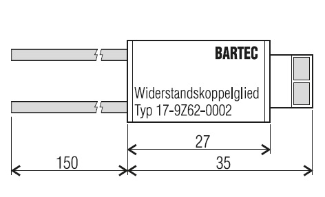
Tips for motstands type (eks. Bartec type: 17-9Z62-0002):